
Written with input from FSE's engineering and systems integration team.
Heavy industrial facilities and mission-critical data centers operate at immense scale. When thousands of high-density server racks or heavy industrial machines function simultaneously, they demand massive, highly stable electrical currents. Managing this electrical power safely requires more than standard circuit breakers. It demands heavy-duty industrial switchgears.
For Chief Technology Officers and VP-level Engineering Directors, understanding the exact mechanical and electrical sequencing of these systems is vital. If an electrical fault occurs on a high-density data floor or a production line, the switchgear is the definitive line of defense between a minor localized reset and millions of dollars in catastrophic hardware damage. By analyzing the precise step-by-step process of how these systems route power and isolate electrical faults, engineering teams mitigate operational risk.
The financial consequences of unoptimized power infrastructure manifest as extended operational downtime and accelerated equipment degradation. When a data center or manufacturing facility experiences a power surge, sensitive control electronics and server blades suffer immediate thermal stress. This guide breaks down the core mechanics of industrial power distribution to help technical leaders protect their capital investments.
What is an Electrical Switchgear?
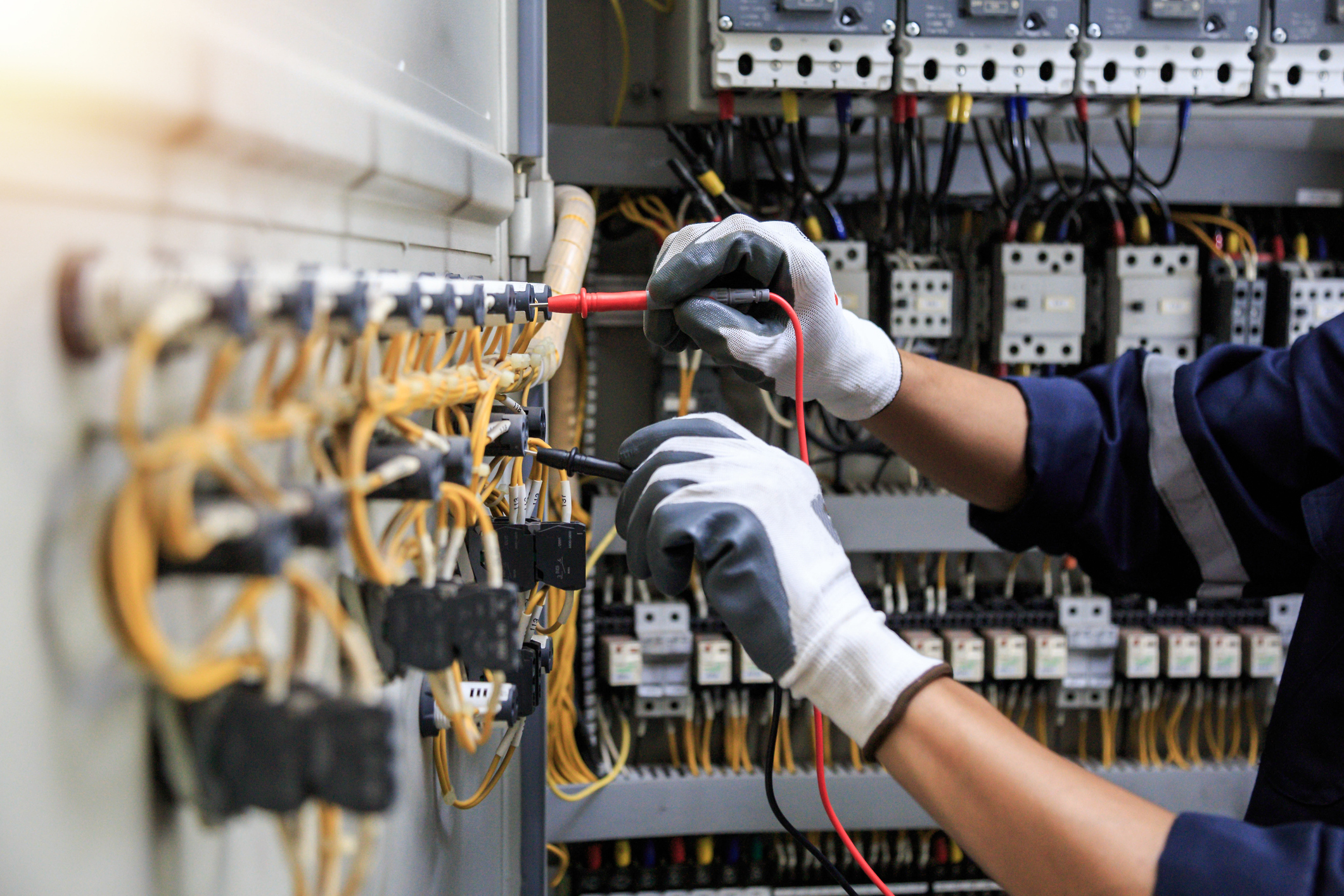
At its core, an electrical switchgear is a centralized collection of circuit disconnect switches, fuses, and circuit breakers housed within a ruggedized metallic enclosure. These industrial assemblies control, protect, and isolate an electrical grid by regulating the distribution of power across different zones of a facility. Switchgears do not simply turn systems on and off; they actively monitor the quality of incoming electricity to maintain a balanced load.
In a data center or industrial ecosystem, the switchgear acts as the primary electrical gatekeeper. It receives high-voltage or medium-voltage power directly from the utility grid or an on-site substation. From there, it normalizes and distributes that power down to individual control panels, power distribution units, and critical infrastructure. This centralized control ensures that power distribution remains highly organized and scalable.
When a system experiences an electrical surge, the switchgear instantly senses the anomaly. It de-energizes the affected circuits within milliseconds, keeping the rest of the facility fully operational. Without this localized protection, a minor electrical fault in a single server rack or industrial machine propagates upstream, causing a complete facility blackout and damaging sensitive microprocessors.
The Step-by-Step Process of Switchgear Operation
To understand how these systems maintain operational continuity, it helps to examine their performance during standard operations and unexpected electrical faults. The entire process relies on a continuous loop of monitoring, detection, interruption, and isolation. This mechanical and digital sequence executes perfectly every single time to ensure total facility safety.
Step 1: Continuous Current Monitoring and Power Routing
During normal operations, the switchgear serves as a passive power distribution hub. Electricity flows through heavy copper or aluminum busbars inside the enclosure, routing power to downstream infrastructure. These busbars handle maximum continuous currents without overheating, ensuring that energy transfer remains highly efficient.
Simultaneously, highly sensitive instrument transformers continually measure the current and voltage levels. These transformers scale down the massive primary currents into small, measurable signals. They feed this real-time electrical data into protective relays, which act as the central brain of the switchgear system, constantly analyzing the electrical health of the plant or data center floor.
Step 2: Fault Detection and Signal Transmission
Imagine a scenario where a data center cooling pump or a heavy industrial motor experiences a catastrophic mechanical jam. The electric motor draws an immediate, massive spike in current to overcome the physical resistance, creating an overcurrent fault. The instrument transformers detect this sudden spike instantly and transmit the elevated measurement data to the protective relay.
The protective relay analyzes the incoming data against predefined safety thresholds. When the current exceeds safe operational parameters, the relay recognizes the event as a dangerous fault condition. It immediately processes the logic and transmits an electrical trip signal to the corresponding circuit breaker, initiating the physical interruption of power.
Step 3: Arc Interruption and Circuit Separation
Once the circuit breaker receives the trip signal, its internal mechanical contacts pull apart to stop the flow of electricity. Because the electrical current is incredibly strong, a high-temperature electrical arc forms across the gap as the contacts separate. This ionized gas arc reaches temperatures hotter than the surface of the sun and requires immediate management.
The switchgear extinguishes this dangerous plasma arc immediately to prevent an internal explosion and protect the physical enclosure. Depending on the design of the switchgear, the system uses specialized mediums such as a vacuum, sulfur hexafluoride gas, or pressurized air to cool and snuff out the arc safely. This rapid suppression preserves the structural integrity of the internal contacts.
Step 4: Localized Fault Isolation
After extinguishing the arc, the switchgear successfully isolates the damaged portion of the electrical system. Because FSE utilizes advanced box build system integration services to design isolated, compartmentalized electrical architectures, the fault remains contained to that single circuit. The physical separation prevents the electrical disturbance from propagating to adjacent equipment.
Power continues flowing uninterrupted to the rest of the facility. The surrounding server racks, cooling infrastructure, and safety networks elsewhere in the building keep running without a single drop in performance. This level of localization allows high-volume industrial environments and data centers to maintain extreme uptime metrics even when individual components encounter physical or electrical failures.
Why Early-Stage Design for Manufacturability Matters
Many engineering teams treat power distribution as an afterthought during the initial facility design phase. They map out the operational layout first, choosing off-the-shelf switchgear enclosures right before deployment. This fragmented procurement approach frequently introduces serious integration bottlenecks, spatial conflicts, and hidden long-term engineering costs.
When you partner with a turnkey contract manufacturer early in the blueprint stage, you eliminate these integration errors. FSE engineers evaluate the exact thermal dynamics, footprint limitations, and peak electrical loads of your machinery or data center equipment before manufacturing begins. This proactive review ensures that the final assembly integrates perfectly with your facility footprint.
Our comprehensive industrial automation systems integrator Maryland team applies advanced Design for Manufacturability (DFM) protocols to optimize your power infrastructure. We analyze component placement, simplify wire routing paths, and ensure compliance with all regional electrical codes. This early-stage intervention reduces manufacturing cycle times and protects your integrated bottom line from field retrofits.
The Technical Reality of Power Distribution Scaling
As industrial facilities and data centers scale, their power requirements grow exponentially. A facility that started with a few server rows or assembly lines evolves into a massive network of interconnected electronics. This scaling process places immense stress on the primary electrical entry points, requiring switchgears that adapt to changing operational demands.
Custom-engineered switchgears accommodate this growth by incorporating modular designs. Engineering teams add distribution sections, upgrade protective relays, and integrate advanced monitoring software without replacing the entire enclosure foundation. This flexibility allows companies to scale their operational capabilities sustainably over time.
Furthermore, integrating advanced digital metering into the switchgear assembly allows facilities to track energy consumption patterns. CTOs utilize this data to optimize machine duty cycles, identify energy inefficiencies, and predict mechanical failures before they cause an electrical fault. This data-driven approach transforms a passive safety asset into a strategic operational tool.
Maximize Your Power Infrastructure Reliability
FSE builds custom power distribution assemblies to ISO 9001 and UL standards, delivering the operational reliability required by mission-critical data centers and heavy industrial operations worldwide.
To protect your infrastructure from critical electrical failures, visit our Contact Us Page to submit your project schematics directly to our engineering team.
FAQs
How often do industrial switchgears require routine maintenance?
Industrial switchgears require visual inspections every six months and comprehensive electrical testing every three to five years. High-dust environments or continuous-load data centers require more frequent cleaning to prevent particulate buildup on critical electrical contacts.
What is the main difference between a switchboard and a switchgear?
Switchgears handle higher voltages, greater current capacities, and more rigorous fault-switching duties than standard switchboards. Switchgears also feature compartmentalized internal barriers that contain electrical faults locally, whereas switchboards house components in a single open space.
Can custom switchgears be integrated into existing infrastructure?
Yes, custom switchgears match the exact dimensions and communication protocols of legacy industrial or data center systems. Retrofitting with custom enclosures allows facilities to upgrade their power handling capabilities without undergoing a complete structural redesign.
Key Takeaways
- Primary Line of Defense: Switchgears combine disconnect switches, fuses, and breakers to protect high-value industrial and data center assets from electrical fault damage.
- Millisecond Response Times: The system operates via a continuous loop where transformers monitor current, relays detect anomalies, and breakers extinguish dangerous electrical arcs in milliseconds.
- Localized Isolation Prevents Downtime: Proper switchgear design guarantees that an electrical failure in one sector will not cause a total facility blackout.
- Proactive Engineering Reduces Cost: Integrating switchgear design early in the infrastructure blueprint phase eliminates field retrofits and optimizes the integrated bottom line.
